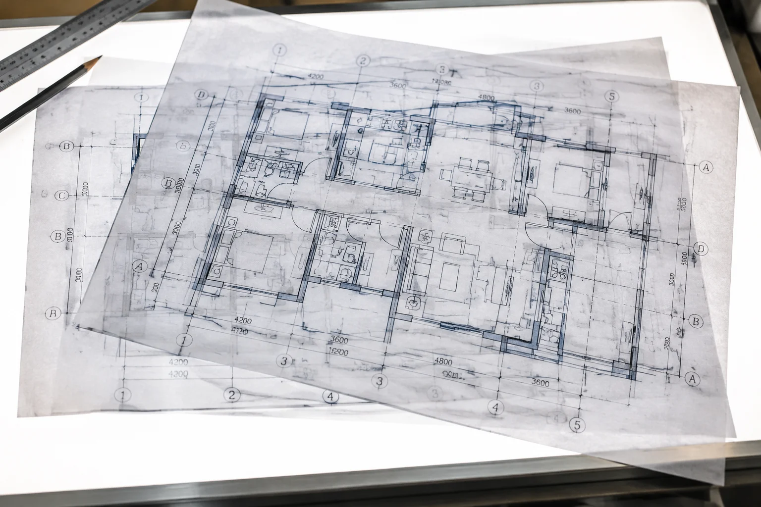
KEY TAKEAWAYS & DRAWING SPECIFICATIONS
DRAWING META & RULES
| ISO Standard | ISO 19650-2:2018 / DIS 19650 |
|---|---|
| Discipline | Cross-Disciplinary Coordination / Architecture & Structure |
| Recommended Scale | 1:50 / 1:100 Site & Core Plans |
| View Template | CASE-COORD-AUDIT-2026 |
CORE METHODOLOGY HIGHLIGHTS
- Unsynchronized shared coordinates corrupt plan view crop regions and false elevation markers across multi-discipline links.
- Discrepancies between Project Base Point and Survey Point generate invisible dimensional creep in compound assemblies.
- Routine publish audits of coordinate transformations eliminate catastrophic clashes prior to site issuance.
01 Anatomy of the Spatial Misalignment Cascade
Coordinate discrepancies rarely manifest immediately during the preliminary modeling phase. When a structural engineer models from an unpinned Project Base Point while the architectural team establishes true north offsets through the Survey Point, initial geometry appears deceptively correct within isolated local viewports. The crisis develops when linked files federate inside central documentation sheets, exposing sub-millimeter offsets that gradually expand across extended building spans.
In complex hospital and commercial developments, these small angle rotations or origin translations disrupt automated dimension strings. Annotations snap inadvertently to linked geometry instead of native model elements, resulting in dual dimension runs on contract drawings. When background reference files shift during scheduled bi-weekly updates, those dependent dimensions either delete automatically or adjust silently, producing inaccurate dimensions on issued site documentation.
A displacement of mere millimeters in the central coordinate origin multiplies into decimeter clashes once structural columns meet precast MEP sleeves on site.
— BIM Coordination Audit Board
02 Systematic Manifestations in Sheet Views and Elevations
The visual impact on issued documentation is destructive. Building sections cut through federated links suddenly exhibit double wall outlines, misaligned floor slabs, and split structural columns. Section markers defined in the architectural package frequently fail to slice through linked structural components at identical spatial planes, rendering detail callouts invalid and obscuring structural bearing conditions.
Elevation view templates suffer comparable failures. Linked mechanical plant equipment modeled on differing coordinate origins displays outside designated roof screens or cuts through solid parapets on sheet layouts. Because view range depth clipping relies on predictable origin planes, shifted models frequently fall outside the active view volume, creating phantom voids where structural framing should appear.
Pin the Project Base Point and Survey Point across all master link sets; never acquire coordinates without a documented site control file verification.
03 Technical Remediation and QA Verification Protocols
Resolving coordinate corruption requires strict procedural discipline rather than ad-hoc repositioning. Lead coordinators must publish an immutable site reference container file containing only master grids, primary datum levels, and audited geodetic survey benchmarks. All consultant models must link this site container and acquire coordinates exclusively from it, locking internal coordinate matrices against casual user tampering.
Drawing quality assurance checks must integrate automated coordinate auditing prior to weekly publishing cycles. Utilizing visual verification templates that highlight intersection points between architectural and structural grid endpoints reveals even a tenth of a millimeter of rotational drift. Establishing this view-checking protocol safeguards drawing sheet integrity and guarantees total spatial consistency between model views and fabricated reality.
RECOMMENDED REVIT VIEW STANDARDS
Ensure your federated models align precisely across all documentation views with our standardized Revit coordinate and view setup checklist.
VIEW THE REVIT GUIDE
DRAWING REVIEW COMMENTS
SUBMIT A TECHNICAL COMMENT
No comments yet. Be the first to leave a comment.