KEY TAKEAWAYS & DRAWING SPECIFICATIONS
DRAWING META & RULES
| ISO Standard | ISO 19650-2:2018 |
|---|---|
| Discipline | Architectural / BIM Coordination |
| Recommended Scale | 1:50 / 1:100 |
| View Template | ARCH_Coordination_Review |
CORE METHODOLOGY HIGHLIGHTS
- Single-view audits frequently miss dimensional conflicts between wall assemblies and door frames across floor plans and section cuts.
- Door schedules must be synchronized with host wall types and fire-rating parameters before issuing tender documentation sets.
- Establishing a standardized three-sheet cross-check protocol reduces field RFIs and costly rework during construction execution.
01 DISSECTING THE THREE-SHEET CROSS-CHECK METHOD
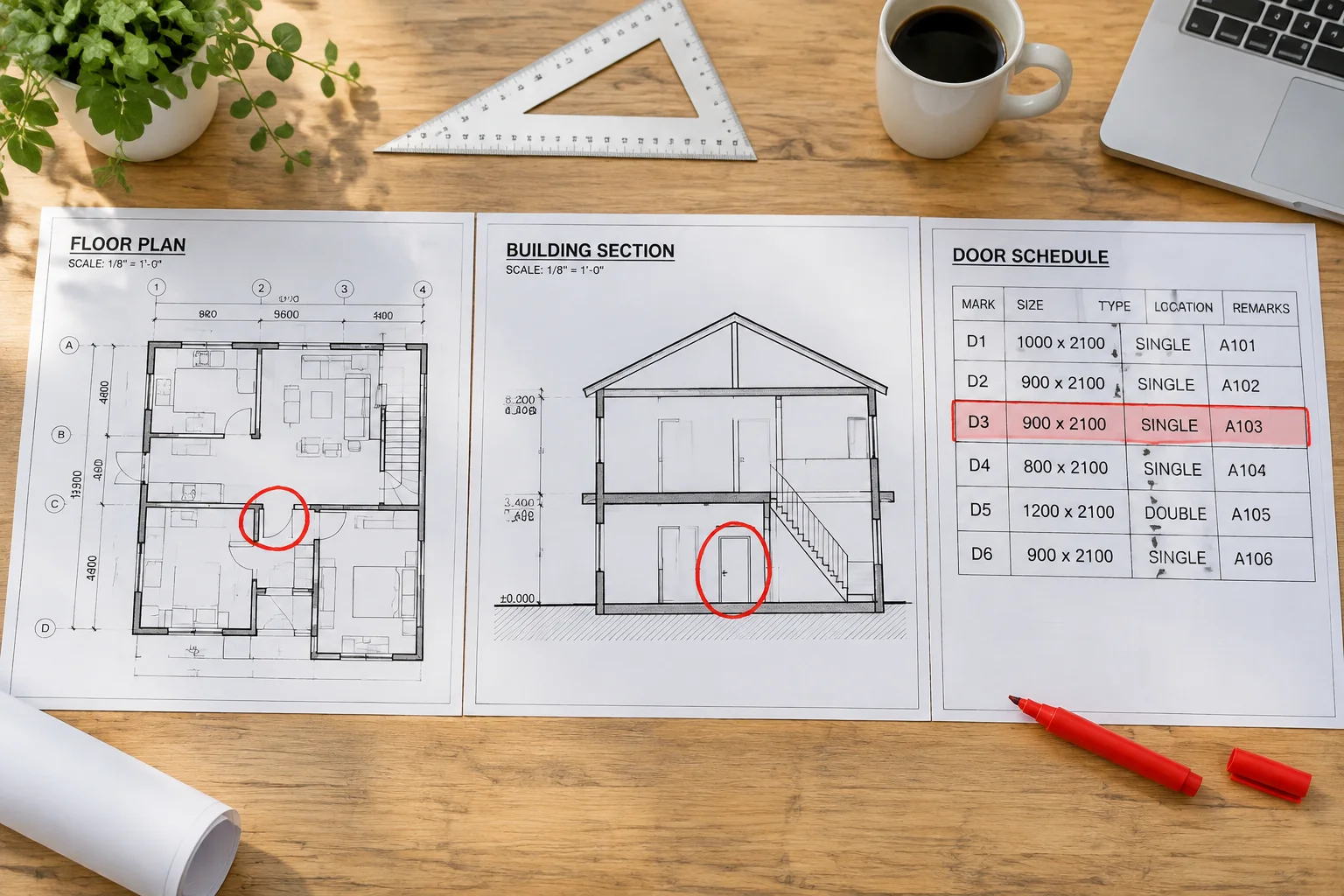
Architectural project documentation frequently suffers from inconsistencies where a single element appears differently depending on the drawing view. During high-volume BIM production, coordinators often review individual sheets in isolation. A floor plan might show a double door swinging outward, while the vertical section view indicates a single leaf frame, and the automated schedule reflects an unassigned fire rating. The three-sheet coordination review addresses this fundamental documentation flaw by establishing a mandatory cross-verification workflow across primary drawing types.
By aligning floor plans, wall sections, and element schedules side-by-side on dedicated review tables—or within multi-monitor BIM coordination workspaces—technicians can systematically verify graphic integrity and metadata fidelity. This tri-directional verification ensures that every callout, detail tag, and spatial boundary is validated simultaneously, reducing the likelihood of mismatched annotations entering final construction deliverables.
The illustrative educational case in this review uses a conditional project containing three sheets:
| Sheet | Contents | Review Focus |
|---|---|---|
| A-101 | Floor Plan | Visibility and scale |
| A-201 | Building Section | Element representation |
| A-601 | Door Schedule | Model information |
A door schedule is not merely a list of elements; it is an active contract between graphic plans, vertical sections, and parametric model metadata.
— Lead BIM Auditor, Documentation Consistency Group
02 IDENTIFYING DISCREPANCIES ACROSS PLANS, SECTIONS, AND SCHEDULES
Discrepancies usually surface when view templates apply conflicting visibility graphics overrides or when instance parameters are manually altered outside established model standards. For instance, a door scheduled with a 90-minute fire resistance rating may be hosted inside a 60-minute partition wall on the floor plan view, while the detail section omit structural lintel clearance notes entirely. Identifying these mismatches requires disciplined examination of both graphic geometry and tabular parameters.
Technical teams must establish audit routines that trace individual tag references across view boundaries. When a door number tag is selected on sheet A-101, auditors must immediately verify its representation on vertical section sheet A-201 and confirm that its width, height, frame material, and hardware set in schedule sheet A-601 match the exact design intent without manual text overrides.
In the educational scenario, a single door is present in the model and correctly listed in the A-601 schedule, yet it does not appear on the A-101 floor plan because of the view's display settings. The correct diagnostic approach is to check the element's category visibility, the view's visibility/graphics overrides, filters, crop region, and view range step by step—without asserting in advance that the discrepancy is caused by any particular software setting. Only a systematic review reveals which display decision hides the door.
Always verify that door parameter filters in view templates do not unintentionally omit scheduled elements or obscure fire-rated wall boundary lines across structural model overlays.
03 PREVENTING DOWNSTREAM ERRORS BEFORE CONSTRUCTION ISSUANCE
Implementing the three-sheet coordination review as a formal milestone before tender release significantly mitigates contractor Requests for Information (RFIs) and field change orders. When spatial dimensions and schedule parameters align seamlessly across all issued sheets, site teams can execute installations without resolving contradictory documentation on site.
Standardizing this workflow fosters tighter collaboration between BIM coordinators and lead architects. By standardizing view presets, parameter naming conventions, and automated schedule filters, design firms ensure long-term drawing accuracy while training junior technicians to recognize complex model view interactions before issuing final drawing packages.
RECOMMENDED REVIT VIEW STANDARDS
Explore our comprehensive Revit View Templates and Drawing Consistency Guide to standardize your team's QA/QC coordination workflow and prevent sheet discrepancies.
VIEW THE REVIT GUIDE
DRAWING REVIEW COMMENTS
SUBMIT A TECHNICAL COMMENT
Laura Palmer
2026-11-06This case study perfectly illustrates the door schedule issue we had last week.
Steve Harrington
2026-11-07Diagnosing visibility without jumping to conclusions is a great skill to teach.